Mini UAV Video Transmission Module HT-SDR-1400-27
HT-SDR-1400-27 is independently developed by Zhongxun Huitong Technology. It adopts a Software Defined Radio (SDR) architecture to realize MESH networking and can be used for different distances by matching power amplifiers of various power levels. It supports MESH networking, with a maximum bandwidth of 20 MHz, a maximum throughput of 47 Mbps, intelligent frequency selection, AES256 encryption, and range extension mode.
产品描述
Product Introduction
HT-SDR-1400-27 Software-Defined Radio (SDR) MESH Networking Module
The HT-SDR-1400-27 is an independently developed SDR-based (Software-Defined Radio) product by Beijing Zhongxun Huitong Technology Co., Ltd., designed for MESH networking.
It supports various power amplifier levels to achieve different transmission ranges.
Main Features
- Supports MESH networking
- Maximum bandwidth up to 20 MHz
- Maximum throughput up to 47 Mbps
- Supports smart frequency selection
- Supports AES-256 encryption
- Supports range extension mode
Key Characteristics
- Supports MESH networking
- Multiple maximum transmit power options: 27 dBm, 30 dBm, 36 dBm, 40 dBm, 46 dBm
- Configurable bandwidths: 5 MHz / 10 MHz / 20 MHz
- Optional 1.4 GHz frequency band (customized version)
- Maximum transmission distance up to 500 km
- Automatic frequency control supported
- Provides 2 Ethernet ports
- Provides 3 serial ports (2 × RS-232, 1 × 3.3 V TTL)
Applications
- Unmanned systems MESH communication
- Long-distance maritime wireless transmission
- Point-to-multipoint medium-range data links
- Power grid and hydrological inspection
- Firefighting and emergency communication systems
Typical Ratings
| Model | Supply Voltage (V) | Max Power Consumption (W) | Max Output Power (dBm) |
|---|---|---|---|
| HT-SDR-1400-30 | 18–28 | 15 ± 5 | 30 |
| HT-SDR-1400-36 | 24–28 | 45 ± 10 | 36 |
| HT-SDR-1400-40 | 24–28 | 80 ± 20 | 40 |
| HT-SDR-1400-46 | 24–28 | 180 ± 25 | 46 |
Frequency Band Configuration
The HT-SDR-1400-XX supports multiple bands (cannot be modified by users).
| Band | Frequency Range |
|---|---|
| 1.4 GHz | 1350 – 1450 MHz |
| TBD | TBD |
Factory default configuration is fixed at 1.4 GHz.
Transmit Power
Available in multiple versions: 30 dBm / 36 dBm / 40 dBm / 46 dBm,
allowing users to select the proper output power for different application scenarios.
Intelligent Frequency Selection
The HT-SDR-1400-XX supports smart frequency hopping.
Each node dynamically scans the spectrum in real-time and automatically adjusts its working frequency based on the interference environment, enabling adaptive, interference-avoiding MESH networking.
Bandwidth Configuration
Supports 5 MHz, 10 MHz, 20 MHz channel bandwidths.
Transmission Distance
Software-configurable distance limit up to 500 km, adjustable according to the actual deployment.
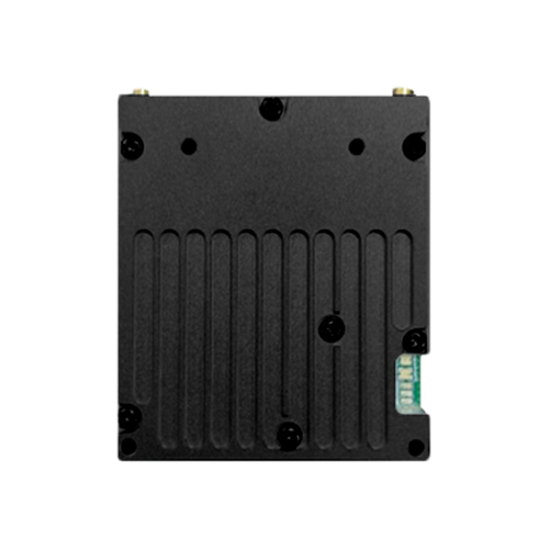
Interface and Indicators
When the digital interface faces downward, indicator LEDs from left to right are:
- LED 1 (Power): Green = power normal; Red = FPGA loading
- LED 2 (Signal Strength): Green > Yellow > Red > Off (strong → weak)
- LED 3 (Link Status): Green = linked; Red = disconnected
- LED 4 (Ethernet 1)
- LED 5 (Ethernet 2)
Interface Details:
| Port | Connector Type | Description |
|---|---|---|
| Power | XT30PW-M | GND, VCC – power supply input |
| Ethernet 1 | PH2.0-4 | RX-, RX+, TX-, TX+ (10/100 M) |
| Ethernet 2 | PH2.0-4 | RX-, RX+, TX-, TX+ (10/100 M) |
| Dual Serial Port | PH2.0-6 | R1, GND, T1, R0, GND, T0 (RS-232 level) |
| Single Serial Port | PH2.0-3 | R2, GND, T2 (TTL 3.3 V level) |
Bandwidth, Sensitivity, and Data Rate Table
| 20 MHz Bandwidth | MCS | 0 | 1 | 2 | 3 | 4 | 5 | 6 | 7 | 8 |
|---|---|---|---|---|---|---|---|---|---|---|
| Single Antenna Sensitivity (dBm) | –101 | –98 | –95 | –92 | –88 | –86 | –83 | –80 | –77 | |
| Dual Antenna Sensitivity (dBm) | –104 | –101 | –98 | –95 | –91 | –89 | –86 | –83 | –80 | |
| SNR (dB) | –8 | –5 | –2 | 4 | 7 | 10 | 13 | 16 | 19 |
UDP Throughput (Mbps)
| Distance Mode | MCS0 | MCS1 | MCS2 | MCS3 | MCS4 | MCS5 | MCS6 | MCS7 | MCS8 |
|---|---|---|---|---|---|---|---|---|---|
| 10 km | 1.5 | 3.2 | 6.4 | 13 | 20 | 26 | 33 | 40 | 47 |
| 30 km | 1.4 | 2.9 | 5.9 | 12 | 18 | 24 | 31 | 37 | 43 |
| 50 km | 1.3 | 2.7 | 5.5 | 11 | 17 | 22 | 28 | 34 | 40 |
| 100 km | 1.1 | 2.4 | 4.7 | 9.6 | 14 | 19 | 24 | 29 | 34 |
| 150 km | 0.9 | 1.9 | 4.0 | 8.3 | 12 | 16 | 21 | 25 | 29 |
| 200 km | 0.8 | 1.7 | 3.6 | 7.4 | 11 | 14 | 18 | 22 | 26 |
| 250 km | 0.7 | 1.5 | 3.2 | 6.6 | 10 | 13 | 16 | 20 | 23 |
| 300 km | 0.6 | 1.4 | 2.9 | 6.0 | 9.1 | 12 | 15 | 18 | 21 |
| 400 km | 0.5 | 1.1 | 2.4 | 5.0 | 7.6 | 10 | 12 | 15 | 18 |
| 500 km | 0.4 | 1.0 | 2.1 | 4.3 | 6.6 | 8.8 | 11 | 13 | 15 |
Note: Throughput for 10 MHz bandwidth ≈ 50% of 20 MHz; Throughput for 5 MHz bandwidth ≈ 25% of 20 MHz.


